An overview of Chaos Wheeled Vehicle Component in Unreal Engine

Welcome to part 2 of the series. We will dive deeper on more customizations available out of the box in the Chaos Wheeled Vehicle Component! (CWVC).
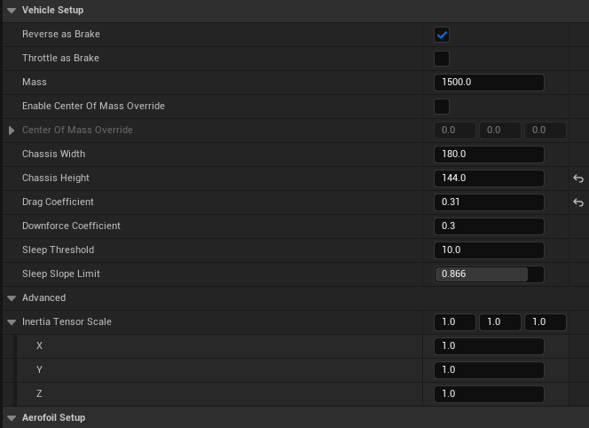
The vehicle setup category is for specifying the high level characteristics of the vehicle, like the mass, the center of mass, the downforce or how much gravity affects us, chassis width, and sleep threshold. We also got the drag coefficient, that is, how much air resistance the vehicle experiences. A higher value means more drag and slower top speed.
Similarly, the downforce coefficient is how much downward force the vehicle generates due to its aerodynamics. Higher values increase grip at high speeds.
Finally we got the inertia tensor scale: A multiplier that affects how the vehicle's mass is distributed around its center of mass, influencing how it rotates and handles.
Let’s get to the aero foils now:
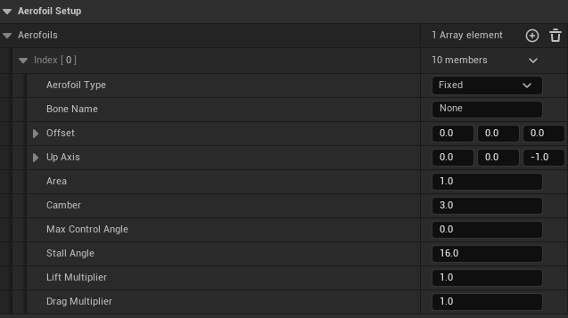
The current aero foil is the default one:
Aero foil Type
Fixed: This means the aero foil's angle cannot be changed during the simulation/game. It's a simple, non-adjustable wing.
Area
1.0: The surface area of the aerofoil. A larger area means it can generate more lift and drag.
Camber
3.0: The curvature of the aerofoil's upper surface. Higher camber generally means more lift but also more drag.
Max Control Angle
0.0: Since the aero foil type is fixed, this value is irrelevant. It would normally define the maximum angle the aero foil could be adjusted to. We could use this to control the thing at runtime with the press of a button, you know.
Stall Angle
16.0: The angle between the aerofoil and the oncoming airflow at which the aerofoil stalls and loses lift. Most aerofoils are between 15-20 degrees.
These settings describe a simple, fixed aerofoil with a downward-facing orientation, centered on the vehicle. It has a moderate camber and a stall angle of 16 degrees. The lift and drag forces are not modified by any multipliers.
This configuration is likely meant to simulate a spoiler or a wing that primarily generates downforce (negative lift) to improve the vehicle's traction at high speeds.
Now let’s go with the type of aero foils:
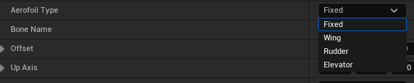
Fixed:
This refers to an aero foil that has a fixed angle of attack, meaning its orientation relative to the oncoming airflow doesn't change.
Fixed aerofoils are typically used to generate consistent lift or downforce throughout the vehicle's operation. Examples include:
Spoilers on the rear of cars to increase traction.
Wings on airplanes to provide lift.
Wing:
This refers to a large aerofoil that is primarily responsible for generating lift, allowing the vehicle to fly or maintain stability in the air.
In airplanes, wings are typically adjustable, allowing the pilot to control the amount of lift generated. In cars, wings are often fixed and designed to generate downforce to improve traction at high speeds.
Rudder:
This is a vertical aerofoil located at the rear of the vehicle, typically used for steering or yaw control.
By deflecting the rudder, the vehicle can change its direction of travel. In airplanes, the rudder is controlled by the pilot's foot pedals. In cars, the rudder might be used to enhance stability during high-speed turns.
Elevator:
This is a horizontal aerofoil located at the rear of the vehicle, typically used for pitch control (tilting the nose up or down).
By deflecting the elevator, the vehicle can change its pitch angle. In airplanes, the elevator is controlled by the pilot's control stick or yoke. In cars, the elevator might be used to adjust the vehicle's attitude during acceleration or braking.
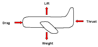
These control surfaces work in concert to allow the vehicle to maneuver through the air or maintain stability. The wing generates lift, the rudder controls yaw (left/right movement), and the elevator controls pitch (up/down movement).
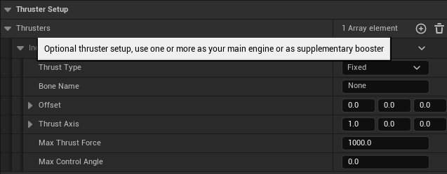
Thruster Setup
This is the main section for configuring thrusters, which provide propulsion to the vehicle. You can have multiple thrusters, serving as main engines or supplementary boosters.
Thrust Type
Fixed: The thruster's direction is fixed and cannot be changed during the simulation. It will always provide thrust in the same direction.
Thrust Axis
1.0, 0.0, 0.0: This defines the direction in which the thruster will apply force. In this case, it's along the positive X-axis, which is usually interpreted as forward in most 3D coordinate systems.

Now let's go to the famous arcade control:
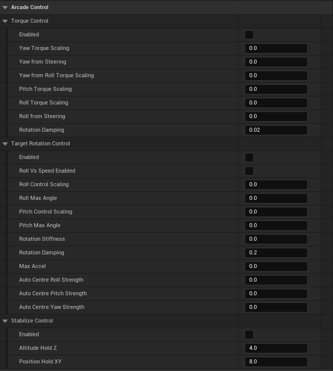
Torque Scaling: Adjusts the strength of the forces applied to the vehicle's rotation around each axis (yaw, pitch, and roll).
Yaw from Steering: Determines how much the steering input affects the vehicle's yaw (turning left/right).
Yaw from Roll Torque Scaling: Influences how the vehicle's roll (tilting sideways) affects its yaw.
Pitch Torque Scaling: Adjusts the force applied to the vehicle's pitch (nose up/down).
Roll Torque Scaling: Adjusts the force applied to the vehicle's roll.
Roll from Steering: Determines how much the steering input affects the vehicle's roll.
Rotation Damping: Controls how quickly the vehicle's rotation slows down when not under acceleration or braking.

Target Rotation Control
Roll Vs Speed Enabled: Controls whether the roll angle of the vehicle is influenced by its speed.
Roll Control Scaling: Adjusts the strength of the roll control system.
Roll Max Angle: Sets the maximum allowable roll angle for the vehicle.
Pitch Control Scaling: Adjusts the strength of the pitch control system.
Pitch Max Angle: Sets the maximum allowable pitch angle for the vehicle.
Rotation Stiffness: Determines how strongly the vehicle resists changes to its rotation.
Rotation Damping: Controls how quickly the vehicle's rotation slows down when not under the influence of the target rotation control.
Max Accel: Sets the maximum acceleration for the target rotation control.
Auto Centre Roll/Pitch/Yaw Strength: Controls the strength with which the vehicle tries to automatically correct its roll, pitch, and yaw angles to neutral.
Stabilize Control
Altitude Hold Z: Determines the target altitude for the stabilization system.
Position Hold XY: Determines the target position in the X and Y axes for the stabilization system.
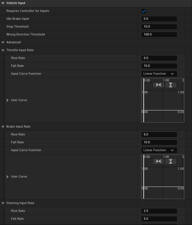
Stop Threshold:
10.0: This sets a threshold for the vehicle's speed below which it's considered "stopped." This could be used for triggering specific behaviors or effects when the vehicle comes to a halt.
Wrong Direction Threshold:
100.0: This determines the speed at which the game considers the vehicle to be moving in the wrong direction (e.g., reversing at a high speed). This could be used to trigger penalties or warnings for the player.
Advanced
Throttle Input Rate:
Rise Rate (6.0): How quickly the throttle input ramps up from 0 to maximum when the player presses the accelerator. A higher value means faster acceleration response.
Fall Rate (10.0): How quickly the throttle input ramps down from maximum to 0 when the player releases the accelerator. A higher value means faster deceleration.
Input Curve Function: Allows you to customize the relationship between the player's input and the actual throttle output using a curve. The default "Linear Function" means a direct, proportional relationship.
Brake Input Rate:
Rise Rate (6.0): How quickly the brake input ramps up when the player presses the brake pedal.
Fall Rate (10.0): How quickly the brake input ramps down when the player releases the brake pedal.
Input Curve Function: Similar to the throttle, this allows for customizing the brake input curve.

Steering Input Rate:
Rise Rate (2.5): How quickly the steering input ramps up when the player turns the wheel or joystick.
Fall Rate (5.0): How quickly the steering input ramps down when the player releases the steering input.

That's all for this part. See you around in The Low Level Bunker!


Comments